INCLINED FIRE
William T. McDonald
June 2003
"Inclined fire" is a shooting situation in which a gun is first sighted in at a shooting range that is level or nearly level, and later must be fired at a target located either upward or downward at some inclination angle and some slant range distance between the shooter and the target. An upward inclination angle is called an elevation angle, and a downward inclination angle is called a depression angle. This is the sort of situation that sometimes confronts a hunter in mountainous terrain with steep hillsides and deep ravines. It is a frequent situation for a soldier or marine in urban combat, or a sniper shooting at distant targets. It also occurs for a law enforcement officer or a SWAT (Special Weapons and Tactics) team member in an urban venue.
In such a situation a gun will always shoot high compared to where it shoots on a level trajectory. How high the gun will shoot varies with both inclination angle and slant range distance to the target. The problem facing the shooter is how to determine how much the impact point of the bullet will change at the inclination angle and slant range distance, and then to adjust his or her aim so that the target is hit. Adjusting the aim can take place in either one of two ways. A hunter will usually aim a little lower for an inclined shot than he or she would aim for a horizontal shot, in order to compensate for the gun shooting higher. A soldier or marine in urban combat would likely do the same, because shots at moving or partially concealed targets must happen quickly. But a military or SWAT team sniper in a situation where there is more time to prepare for the shot would probably dial a come-up or come-down on his telescope sight, after calculating the correct aiming adjustment.
To use either of these techniques the shooter must know where the bullet will be relative to the line of sight through the sights on the gun at the slant range distance to the target. In other words, the shooter must know what we call the Bullet Path, that is, the distance between the line of sight and the position of the bullet at the slant range distance of the target. Bullet Path is always measured PERPENDICULAR TO THE LINE OF SIGHT. It is positive when the bullet is above the line of sight, and negative when the bullet is below the line of sight. A convenient mental picture of Bullet Path is where the shooter would "see" the rear end of the bullet, if he or she could watch the bullet through the gun sight as it flies the trajectory. We make a careful distinction between Bullet Path and Bullet Drop. Drop is the VERTICAL distance between the extended bore line of the gun and the position of the bullet, at the slant range distance of the target. It is very important to keep in mind that Bullet Path and Drop are not the same, and the shooter needs to know Bullet Path, not Drop, in order to aim the gun.
Of course, in any shooting situation the first step is to measure or estimate the inclination angle and the slant range distance to the target. There are instruments to measure both these parameters, if the shooter (or a team mate) has time to use the instruments in the shooting situation. Otherwise estimates must suffice. But, knowing these parameters, the shooter also must have some means of computing the correct aiming adjustment. And unfortunately, a computation is absolutely necessary for accurate fire when the angle is steep and/or the range distance is long.
The Sierra Infinity exterior ballistics computer program will calculate the trajectory of the bullet for any inclination angle. Given the slant range distance to the target, the software then provides the correct aiming adjustment (the come-up or come-down) to place the bullet on the target. This trajectory calculation is made considering that the gun has been sighted in on a level range. However, in all but a very few field situations it is just not practical for the hunter, military person, SWAT team, or sniper team to carry a computer for this purpose. So, a method is necessary to calculate approximate but reasonably accurate aiming adjustments on something no larger than a hand-held engineering calculator, that is, a calculator that performs arithmetic and trigonometric calculations.
Any error made in calculating or estimating the aiming adjustment for inclined fire will be systematic rather than random in nature. What this means is that, for any given situation (a given inclination angle and slant range distance to the target), the aiming error will be the same for every round fired, unless the shooter makes some further aiming adjustments between shots based on observed misses. But in most shooting situations for hunters, military, or law enforcement personnel, the first shot must count; there is little chance of a second shot to correct a miss observed on the first shot.
Of course, some aiming error is tolerable, depending on the shooting scenario. For a hunter after, say, deer in mountainous terrain, inclination angles can be quite steep, but generally not more than about 45o, and slant range distances can be up to around 400 yards. The hunter typically would like to place his bullet within about an 8-inch circle just behind the front leg of the deer to hit the heart or lung and put the deer down. This limits the tolerable error in bullet placement to about 4 inches vertically on the skin of the deer. That error is multiplied by the cosine of the inclination angle when viewed by the shooter, so that the aiming error after the aiming adjustment can be no more than about 3 inches at the slant range distance from the hunter to the animal.
In an urban warfare venue a soldier can be on a street engaging enemies in windows in high buildings or on rooftops, or vice versa. In such cases inclination angles can be very steep and partially concealed targets very small, but ranges are usually short, often less than 100 yards. The Bullet Path inaccuracy cannot be more than about 2 inches in such situations. Law enforcement SWAT teams typically have similar situations in urban environments, but sometimes with longer slant range distances and inclination angles not quite so steep. However, accuracy requirements are even tighter because of hostages or bystanders. The error in the calculated aiming adjustment cannot be more than about 1 inch in such situations.
There are at least three methods of calculating approximate aiming adjustments in use presently. The purpose of this article is to evaluate the accuracy of each of these methods by comparing the aiming adjustment (come-up, come-down, holdover, holdunder) resulting from each method with the adjustment calculated by Sierra's Infinity program. We have designed the trajectory calculations in Infinity to be highly accurate, so we believe it is a suitable reference to evaluate the accuracy of each approximate method. We begin first by explaining what Infinity does, which also will serve to explain the problem of inclined fire graphically. Then, we will proceed to the accuracy evaluation for a specific rifle and cartridge combination and some specific shooting scenarios.
A shooter begins by sighting in his or her gun on a nearly level (horizontal) shooting range, as shown in Figure 1 below. Sighting in simply makes the bullet trajectory cross the Line of Sight (LOS) at the zero range, which is the position of the target. The barrel of the gun is tilted upward by a small superelevation angle to make this happen. This angle is typically less than 1.0 degree for modern cartridges and practical range distances. Infinity very accurately calculates the superelevation angle and all the trajectory parameters for this level fire situation. Bear in mind that all the figures below are not to scale and greatly exaggerated to illustrate the points of discussion.

Figure 1. Level Fire Trajectory for Sighting In
For inclined fire, the Infinity user points and clicks on the "Up Hill - Down Hill" operation in the "Operations" drop-down menu and enters an inclination angle. Suppose the user enters a positive inclination (elevation) angle. Infinity will then calculate a trajectory for the situation illustrated in Figure 2.
The horizontal axis is rotated upward by the elevation angle, and the vertical axis is also rotated by the same angle. The line of sight follows accordingly; the Sight Height is constant, because when the shooter aims uphill the gun sights are the same distance above the bore line as they were in the horizontal situation. And with no changes in the gun sights the LOS crosses the rotated horizontal axis at the same zero range distance from the shooter, although the elevated trajectory is no longer zeroed at this point.

Figure 2. Inclined Trajectory Situation
For this situation Infinity uses the same superelevation angle that was calculated for the level fire trajectory. Infinity very accurately calculates the elevated trajectory, including Drop and Bullet Path. Both Figure 2 and Figure 3 show the Drop, Bullet Path, and height of the LOS at a given slant range distance R. Figure 3 is a close-up view of these trajectory parameters at R to more clearly illustrate the relationships. Again bear in mind that these figures are greatly exaggerated for illustrative purposes. Drop, Bullet Path, and LOS Height are measured in inches or centimeters, while range distances are measured in hundreds of yards or meters.
According to the conventions that we use, Drop is always measured in the VERTICAL direction, because almost all targets stand vertically; Bullet Path is measured PERPENDICULAR TO THE LOS; and the LOS Height is measured perpendicular to the Rotated Horizontal Axis, as more clearly depicted in Figure 3. The figures exaggerate the relatively small differences in the slant range distances from the shooter to the intersection points on the Inclined Trajectory and the other rotated lines in Figures 2 and 3. For example, if a shooter wishes to place a bullet accurately on a target at a slant range distance R along the line of sight, from Figure 3 the shooter would simply use a come-down equivalent to the Bullet Path calculated by Infinity. At a slant range

Figure 3. Close-up View of Inclined Trajectory at Slant Range R
distance longer than the point at which the trajectory crosses the line of sight, Infinity would give a negative Bullet Path and the shooter would use the equivalent come-up.
As stated earlier, Infinity is very accurate but impractical for use in the field. So, a practical method of calculating aiming corrections is needed. Three such methods are currently used. Each method will be described and its accuracy will be evaluated below. First, however, this writer would like to especially acknowledge and thank three individuals who have motivated and contributed to the information in this article. The first is Mr. Lou Schweibert, President of Schweibert Precision (Ballisticard SystemsTM www.ballisticards.com) of Atascadero, CA, U. S. A. Mr. Schweibert has corresponded with this writer about several topics in ballistics and has permitted this writer to review a paper of his concerning the first method. The second person is Mr. Ruben Nasser of Asuncion, Paraguay, who has corresponded with this writer about several ballistics topics including inclined fire, initially described the second method, and introduced this writer to the third individual. This third person is Mr. Mike Brown of Austin, TX, U. S. A. Mr. Brown has written a very interesting paper (as yet unpublished in June 2003) analyzing both the first and second methods, and also has corresponded with this writer. All three of these individuals have made substantial contributions to the knowledge base of this writer concerning inclined fire, and this writer is very grateful.
First Method for Aiming Adjustment: Rifleman's Rule
No one seems to know who invented the first practical method of calculating aiming corrections for inclined fire. It has been known for a long time by names such as "Rifleman's Rule," "Quick Fix," and perhaps others. Analyses of this method appear in the book Modern Exterior Ballistics by Robert L. McCoy, and also in the unpublished paper "The Rifleman's Rule - Revisited" by Mike Brown. These analyses are based on bullet trajectories in a vacuum (no aerodynamic drag), because in a vacuum the trajectory variables of a bullet can be expressed by closed form mathematical equations. This makes the problem amenable to pencil and paper analysis, but substantial errors can be expected because a vacuum trajectory is really a gross approximation to the actual trajectory of a bullet, which cannot be expressed in closed form equations. The Rifleman's Rule (RR) Method derived by these analyses is the following:
1. Measure the inclination angle of the target above or below the horizontal direction.
2. Measure the slant range distance to the target.
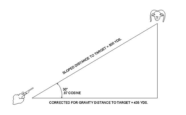
3. Multiply the slant range distance by the trigonometric cosine of the inclination angle (this gives the horizontal projection of the slant range).
4. Use the Bullet Path (or come-up or come-down) from the level trajectory at this horizontal projection distance to adjust the aim for the inclined target.
In other words, pretend that the inclined target is at a horizontal distance equal to the slant range distance multiplied by the cosine of the inclination angle, and aim as if the target were really at that horizontal position.
Second Method for Aiming Adjustment: Improved Rifleman's Rule
The second method of calculating aiming corrections for inclined fire has been called the "Improved Rifleman's Rule" in the paper by Mike Brown. The inventor of this method also is unknown, although Mr. Brown and Mr. Nasser cite Mr. Tiro Fijo of Paraguay for suggesting the method. In his paper Mr. Brown has analyzed the method, again based on bullet trajectories in a vacuum. This Improved Rifleman's Rule (IRR) Method is the following:
1. Measure the inclination angle of the target above or below the horizontal direction.
2. Measure the slant range distance to the target.
3. Take the Bullet Path (or come-up or come-down) from the level trajectory at a horizontal distance equal to the slant range distance, and multiply that parameter by the cosine of the inclination angle.
4. Use the result of this calculation to adjust the aim of the gun at the inclined target.
Third Method of Aiming Adjustment: Sierra's Approach
The third method of calculating aiming corrections for inclined fire was discovered by this writer and has been published in the Sierra Bullets Reloading Manuals since about 1985. It is not known with certainty that this method originated with this writer, but it was discovered independently. It was based on an observation made with the aid of the exterior ballistics software programs that Ted Almgren and this writer created at that time. The observation was (and is) that bullet Drop at any given slant range distance on inclined trajectories changes very little from the Drop at the equivalent horizontal range distance on a level trajectory. This observation in turn led to the third method of calculating aiming corrections for inclined fire:
1. Measure the inclination angle of the target.
2. Measure the slant range distance to the target.
3. From the level trajectory at a horizontal distance equal to the slant range distance, take both the Drop and Bullet Path.
4. Change the algebraic sign on the Drop number (because Drop is always negative in Infinity change it to a positive number). Then, multiply this positive number by the quantity [1.0 - cosine (inclination angle)].
5. Algebraically add the result of step (4) to the Bullet Path (remembering that Bullet Path can be either a positive or negative number in Infinity) to obtain an adjusted Bullet Path. Then use this result to adjust the aim of the gun at the inclined target.
Accuracy Evaluation of the Methods
The accuracy of each of the three methods will be evaluated by comparing the aiming adjustment produced by the method with the aiming adjustment calculated by Infinity, which will be taken as the "true" aiming adjustment. A particular rifle, cartridge, and shooting situation have been chosen to facilitate the accuracy evaluation. The rifle is a bolt action chambered for the 7.62 x 51 mm NATO (308 Winchester) cartridge loaded with Sierra's 30 caliber 168 grain Hollow Point Boat Tail Match bullet at 2650 fps muzzle velocity. The telescope sight will be assumed to have a large objective lens, so that the Sight Height (distance between the centerline of the telescope and centerline of the bore) will be taken as 1.75 inches. The firing point altitude will be set at 3000 ft above sea level, because we will evaluate accuracy for depressed fire as well as elevated fire. The atmospheric conditions will be the Standard Metro conditions adjusted to the firing point altitude, and with no winds. It will be assumed also that the rifle is sighted in at a zero range distance of 100 yards on a level range at 3000 ft altitude and with the same atmospheric conditions, so that the comparisons for inclined fire will not need to be adjusted for changes in altitude or weather conditions. The accuracy evaluation will be performed to a maximum slant range distance of 1000 yds from shooter to target, although this range is very improbable at steep angles.
This evaluation will be carried out in English units rather than metric units, with apologies to readers accustomed to metric units. Table 1 lists Drop and Bullet Path parameters for the level fire trajectory. These parameters are used for the computations in the three methods of aiming adjustments. A high degree of precision is used for all the parameters discussed in this evaluation (tenths of an fps, hundredths of an inch, hundredths of an MOA). The reason is that we will be comparing large numbers to arrive at small differences. Of course, we are well aware that the value of one "click" on a telescope sight is 1/4 MOA, sometimes 1/8 MOA, but the more precise numbers allow more precise comparisons.
Remaining Velocity, while not required for the evaluation, is listed for reference purposes in Table 1. Actually, Remaining Velocity at any given range distance changes very little with inclination angle. For example, at an elevation angle of 60o the Remaining Velocity at 1000 yds slant range distance is 1175.1 fps, just 2.5 fps faster than the 1172.6 fps at 1000 yds horizontal range distance for the level fire case. For a depression angle of 60o the Remaining Velocity at 1000 yds slant range distance is 1170.6 fps, just 2.0 fps slower than for level fire. These differences are caused primarily by the changes in air density as the bullet climbs or falls. The 60o inclination angle is a worst case (among the four inclination angles considered) for the terminal velocity differences; the differences are smaller at any given range distance for lower inclination angles.

As Tables 1 through 8 show, the range distances chosen for the evaluation are grouped nearer to the firing point and then farther from the firing point, with a single range distance in the middle at 500 yds. This is because the aiming errors are most important at shorter ranges for some shooting situations, while in other situations they are very important at longer ranges. These choices also show how the aiming errors for each method vary with range distance. Note that we have chosen one range distance, 875 yds, for the tables because the maximum effective range for the sniper rifles presently used by the U.S. Army (M24) and U.S. Marine Corps (M40A3), both using the 7.62 x 51 mm NATO cartridge, is 800 meters (875 yds).
Concerning the Bullet Path parameter in Tables 1 through 5, a positive value denotes that the bullet is above the LOS, while a negative value shows that the bullet is below the LOS. If the Bullet Path is positive at some given range distance, a come-down is necessary to lower the bullet impact point to the LOS. If the Bullet Path is negative at some range distance, a come-up is required to raise the bullet impact point to the LOS. In all the tables a come-down is shown as a negative come-up, and a notation (Dn) is placed beside the numerical value to signify that it is a come-down. To the right of each Bullet Path column in each table is a column listing the corresponding come-up in MOA (Minutes of Angle). If the Bullet Path value is negative for some given value of range distance, then with no change in the rifle sights the bullet would pass below the LOS by the listed number of inches. A come-up adjustment to the rifle sights by the number of MOA listed in the column to the right of the Bullet Path then is necessary to move the bullet impact point upward to the LOS at the given range distance.


Tables 2 through 5 compare the trajectories computed by Infinity with the aiming adjustments calculated using each of the three methods described above for the inclination angles 15o, 30o, 45o, and 60o, respectively. Then, Tables 6, 7, and 8 show the errors in the calculated aiming adjustments versus slant range distance and versus inclination angle for all three methods. These are the aiming errors that remain AFTER the aiming adjustments calculated by each method are made. To understand more clearly, consider the RR Method used for a 15o inclination angle and a target at 500 yds slant range distance from the shooter. From Table 2 the RR Method calls for a come-up (10.35 MOA) to move the bullet impact point upward 54.21 inches to be on the LOS at the 500 yds slant range distance. Table 2 also shows that Infinity requires a true come-up (10.87 MOA) to move the bullet impact point 56.89 inches upward at the same slant range distance for a trajectory elevated at +15o. If the gun sights are adjusted to move the bullet up 54.21 inches, or if the shooter holds over the target by 54.21 inches, then when the round is fired the bullet will strike 2.68 inches below and perpendicular to the shooter's LOS. This aiming error (or miss in case of a round fired) is shown in the second column of Table 6 for 500 yds slant range and +15o inclination angle. This same calculation performed for a trajectory depressed at -15o results in a 2.46 inch aiming error (or miss) for the RR Method at 500 yds slant range distance, and this is shown in column 3 of Table 6.


In the remainder of this article we wish to focus attention on some key observations from these data. The first is that for any given inclination angle value the trajectory for elevated fire is very little different from the trajectory for depressed fire. This may be seen in Tables 2 through 5 by comparing values in column 2 (Bullet Path for elevated fire) with corresponding values in column 4 (Bullet Path for depressed fire). For example, the worst case is for an inclination angle of 45o and at 1000 yds slant range distance (see Table 4). The difference in the Bullet Path values between the elevated (+ 45o) trajectory and the depressed (- 45o) trajectory is 3.68 inches compared to a total Bullet Path magnitude of approximately 270 inches. This is a very small difference at the 1000 yds slant range distance. And this difference is much smaller at shorter range distances.
It is also true in all cases that the depressed trajectory is a little flatter (Bullet Path magnitude is a little less) than the elevated trajectory. This is caused mainly by a component of the drag force on the bullet acting in the upward vertical direction for a depressed trajectory. This upward-directed force component keeps the bullet on the downward trajectory from falling quite as fast compared to the bullet on the upward trajectory. On the upward trajectory the component of drag force in the vertical direction is directed downward, causing the bullet to fall a little faster as it flies.
Another observation is that the errors in the aiming adjustments calculated by all three methods grow rapidly as the inclination angle grows steeper and the slant range distance grows longer. This can be seen in Tables 6, 7, and 8. This has been known for a long time; the numbers in the tables simply confirm this fact.
Let us imagine a few practical shooting situations. As mentioned above, in an urban warfare or SWAT team situation very accurate bullet placement on targets is necessary. Furthermore, inclination angles can be very steep, but then the slant ranges are quite short. For example, if the firing point is on top of a 20-story building, approximately 200 feet tall (10 feet per story), shooting downward at a -45o angle involves a slant range distance to a target on the ground of only about 94 yds. Shooting downward at -60o shortens the slant range distance to 77 yds. Tables 6 and 7 show that the RR and IRR Methods will have aiming errors under 1.0 inch at -45o, and no more than 1.5 inches at -60o, at these range distances. Table 8 shows that Sierra's Method produces zero aiming errors for both angles at the short slant range distances.
In a hunting situation in mountainous terrain inclination angles larger that 30o are seldom encountered, but an angle as large as 45o might be encountered when hunting game such as mountain goats, mountain sheep, or mouflon in certain parts of the world. In such a situation a hunter needs an aiming error no larger than 3 inches at slant ranges up to 400 yds. Interpolating from Table 6 shows that the RR Method is not accurate enough for 400 yds at 30o, but would be appropriate for a little more than 300 yds at that angle. From Table 7 we conclude about the same accuracy performance for the IRR Method. Table 8 shows that Sierra's Method would suffice for slant ranges well beyond 400 yds and for inclinations even greater than 45o, should such conditions be encountered.
For long range military sniping situations, inclination angles are not large; 30o is likely the limit. But slant range distances can be up to 875 yds. Tolerable aiming error is probably about 8 inches for targets at these limits for inclination angle and range distance. Table 6 shows that the RR Method does not meet this accuracy requirement. Table 7 shows that the IRR Method is marginally accurate, but probably acceptable. Table 8 shows that Sierra's Method exceeds the accuracy requirement by a substantial margin.
In fact, the tables show that of the three methods considered, Sierra's Method appears to produce the most accurate aiming adjustments for all range distances and inclination angles. It is true, though, that the accuracy evaluation must be performed for the intended shooting scenario. Accuracy is not the sole criterion for selection of the method to be used for a specific scenario. If more than one method is sufficiently accurate, then the selected method should be the easiest one to use in the field situation. Sierra's Method is not difficult to use, but it may not be the easiest.
Many other comparisons and observations can be made from the data in the tables, but these are best left to the interested reader. It is important to mention once again that this analysis has been carried out for just one cartridge in several possible scenarios. This cartridge is widely used for most of the shooting scenarios addressed. An exception is the hunting scenario. Match bullet types are not recommended for hunting. But the analytical approach in this article is valid for an inclined fire accuracy evaluation of any cartridge combination.